
Pose Frame Semantics
Current behavior
NOTE: The behavior noted in the
Pose Frame Semantics Proposal
has been implemented in SDFormat 1.7 (libsdformat 9.x). The content of this
proposal will be migrated to this document; in the meantime, please refer to
the proposal.
Legacy behavior
In version 1.4 and earlier of the SDF spec, the <pose> element represents
a relative coordinate transformation between a frame and its parent.
Link frames were always defined relative to a model frame and joint frames
relative to their child link frames.
In version 1.5 of the SDF spec, the frame attribute string was added to
<pose> elements to allow poses to be defined relative to a named frame
instead of the default frames from version 1.4.
For example, this would allow an SDF model to define its kinematics like a
URDF, with joint frames defined relative to the parent link frame and
a joint's child link frames relative to the joint frame.
The 1.5 specification also adds <frame> elements which can define named coordinate
frames in addition to the existing link and joint frames in the model.
This document is a work in progress to define the semantics of the pose frame attribute.
Element naming rules in SDFormat 1.4
In SDFormat 1.4, sibling elements of the same type must have unique names. For example, the following models are invalid because links, joints, and collisions with the same parent do not have unique names.
<sdf version="1.4">
  <model name="model">
    <link name="link"/>
    <link name="link"/> <!-- INVALID: Same name as sibling "link"! -->
  </model>
</sdf>
<sdf version="1.4">
  <model name="model">
    <link name="link1"/>
    <link name="link2"/>
    <link name="link3"/>
    <joint name="joint" type="fixed">
      <parent>link1</parent>
      <child>link2</child>
    </joint>
    <joint name="joint" type="fixed"> <!-- INVALID: Same name as sibling "joint"! -->
      <parent>link2</parent>
      <child>link3</child>
    </joint>
  </model>
</sdf>
<sdf version="1.4">
  <model name="model">
    <link name="link">
      <collision name="collision">
        ...
      </collision>
      <collision name="collision"> <!-- INVALID: Same name as sibling "collision"! -->
        ...
      </collision>
    </link>
  </model>
</sdf>
The following model contains collision elements with the same name, but the models are valid because the elements are not siblings, but rather children of different links.
<sdf version="1.4">
  <model name="model">
    <link name="link1">
      <collision name="collision">
        ...
      </collision>
    </link>
    <link name="link2">
      <collision name="collision"> <!-- VALID -->
        ...
      </collision>
    </link>
  </model>
</sdf>
Sibling elements of different types are not mandated to have unique names, so the following is valid, though it is confusing and not recommended.
<sdf version="1.4">
  <model name="model">
    <link name="base"/>
    <link name="attachment"/>
    <joint name="attachment" type="fixed"> <!-- VALID, but RECOMMEND AGAINST -->
      <parent>base</parent>
      <child>attachment</child>
    </joint>
  </model>
</sdf>
It is allowed to create a link named world, but there is special treatment
for a joint with world specified in the <parent> or <child> tags,
so it is not recommended to do so.
<sdf version="1.4">
  <model name="model">
    <link name="world"/> <!-- VALID, but RECOMMEND AGAINST -->
    <link name="world_link"/> <!-- VALID, better -->
  </model>
</sdf>
Parent frames in SDFormat 1.4
With the exception of joint frames, all <pose> tags in SDFormat 1.4 define
a relative transform between the current element's frame and the frame of its
parent xml element.
For example, in the following model, the link frame is defined relative to the model frame, and the inertial, collision, visual, and sensor frames are all defined relative to the link frame.
<sdf version="1.4">
  <model name="model">
    <pose>...</pose>
    <link name="link">
      <pose>...</pose>
      <inertial>
        <pose>...</pose>
      </inertial>
      <collision name="collision">
        <pose>...</pose>
      </collision>
      <visual name="visual">
        <pose>...</pose>
      </visual>
      <sensor name="sensor">
        <pose>...</pose>
      </sensor>
    </link>
  </model>
</sdf>
The one exception is the joint frame, which is defined relative to the child
link frame. In the following example, the joint frame is defined relative
to the link frame of link2.
<sdf version="1.4">
  <model name="model">
    <pose>...</pose>
    <link name="link1">
      <pose>...</pose>
    </link>
    <link name="link2">
      <pose>...</pose>
    </link>
    <joint name="joint" type="fixed">
      <pose>...</pose>
      <parent>link1</parent>
      <child>link2</child>
    </joint>
  </model>
</sdf>
Given this longstanding behavior, this pattern should be followed for SDFormat 1.5+ when the pose frame attribute is empty. This would imply that the following models are equivalent to the previous models discussed in this section:
<sdf version="1.5">
  <model name="model">
    <pose frame=''>...</pose>
    <link name="link">
      <pose frame=''>...</pose>
      <inertial>
        <pose frame=''>...</pose>
      </inertial>
      <collision name="collision">
        <pose frame=''>...</pose>
      </collision>
      <visual name="visual">
        <pose frame=''>...</pose>
      </visual>
      <sensor name="sensor">
        <pose frame=''>...</pose>
      </sensor>
    </link>
  </model>
</sdf>
and
<sdf version="1.5">
  <model name="model">
    <pose frame=''>...</pose>
    <link name="link1">
      <pose frame=''>...</pose>
    </link>
    <link name="link2">
      <pose frame=''>...</pose>
    </link>
    <joint name="joint" type="fixed">
      <pose frame=''>...</pose>
      <parent>link1</parent>
      <child>link2</child>
    </joint>
  </model>
</sdf>
Parent frames in URDF
For comparison, the behavior of parent frames in Unified Robot Description Format (URDF) is given in this section. A URDF file contains links, joints, collisions, visuals, and inertials like SDFormat, but with several significant differences.
The first difference is that coordinate transformations are expressed using
the attributes of the <origin/> tag instead of the value of <pose/>,
which is a superficial difference as the numerical contents of each tag have a
similar definition.
<pose>x y z roll pitch yaw</pose>
is equivalent to
<!-- URDF -->
<origin rpy='roll pitch yaw' xyz='x y z'/>
Similar to SDFormat, URDF inertial, collision, and visual elements are defined
relative to their parent link frame with their own <origin/> tag, but links
and robots (equivalent to models) do not have <origin/> tags:
<sdf version="1.4">
  <model name="model">
    <link name="link">
      <inertial>
        <pose>...</pose>
      </inertial>
      <collision name="collision">
        <pose>...</pose>
      </collision>
      <visual name="visual">
        <pose>...</pose>
      </visual>
    </link>
  </model>
</sdf>
is equivalent to
<!-- URDF -->
<robot name="model">
  <link name="link">
    <inertial>
      <origin rpy='...' xyz='...'/>
    </inertial>
    <collision name="collision">
      <origin rpy='...' xyz='...'/>
    </collision>
    <visual name="visual">
      <origin rpy='...' xyz='...'/>
    </visual>
  </link>
</robot>
The most significant difference between URDF and SDFormat coordinate frames
is related to links and joints.
While SDFormat allows kinematic loops with the topology of a directed graph,
URDF kinematics must have the topology of a directed tree, with each link
being the child of at most one joint.
URDF coordinate frames are defined recursively based on this tree structure,
with each joint's <origin/> tag defining the coordinate transformation from
the parent link frame to the child link frame.
<sdf version="1.4">
  <model name="model">
    <link name="link1"/>
    <link name="link2"/>
    <joint name="joint" type="fixed">
      <pose>{xyz} {rpy}</pose>
      <parent>link1</parent>
      <child>link2</child>
    </joint>
  </model>
</sdf>
is decidedly not equivalent to
<!-- URDF -->
<robot name="model">
  <link name="link1"/>
  <link name="link2"/>
  <joint name="joint" type="fixed">
    <origin xyz='{xyz}' rpy='{rpy}'/>
    <parent link="link1"/>
    <child link="link2"/>
  </joint>
</robot>
The following image is used in URDF documentation to illustrate how coordinate frames are defined recursively from link1 -> joint1 -> link2 and link1 -> joint2 -> link3 -> joint3 -> link4:
This model in this image could be represented by the following URDF
with model frame M, link1 frame L1, link2 frame L2,
joint1 frame J1, etc.
using the suffix notation for kinematic quantities described in the
specify_pose tutorial.
<!-- URDF -->
<robot name="model">

  <link name="link1"/>

  <joint name="joint1" type="revolute">
    <origin xyz='{xyz_L1L2}' rpy='{rpy_L1L2}'/>
    <parent link="link1"/>
    <child link="link2"/>
  </joint>
  <link name="link2"/>

  <joint name="joint2" type="revolute">
    <origin xyz='{xyz_L1L3}' rpy='{rpy_L1L3}'/>
    <parent link="link1"/>
    <child link="link3"/>
  </joint>
  <link name="link3"/>

  <joint name="joint3" type="revolute">
    <origin xyz='{xyz_L3L4}' rpy='{rpy_L3L4}'/>
    <parent link="link3"/>
    <child link="link4"/>
  </joint>
  <link name="link4"/>

</robot>
For comparison, here is an SDFormat model with the same link names, joint names, frame names, and parent-child relationships.
<model name="model">
  <link name="link1">
    <pose>{xyz_ML1} {rpy_ML1}</pose>
  </link>
  <link name="link2">
    <pose>{xyz_ML2} {rpy_ML2}</pose>
  </link>
  <link name="link3">
    <pose>{xyz_ML3} {rpy_ML3}</pose>
  </link>
  <link name="link4">
    <pose>{xyz_ML4} {rpy_ML4}</pose>
  </link>
  <joint name="joint1" type="revolute">
    <pose>0 0 0 0 0 0</pose>
    <parent>link1</parent>
    <child>link2</child>
  </joint>
  <joint name="joint2" type="revolute">
    <pose>0 0 0 0 0 0</pose>
    <parent>link1</parent>
    <child>link3</child>
  </joint>
  <joint name="joint3" type="revolute">
    <pose>0 0 0 0 0 0</pose>
    <parent>link3</parent>
    <child>link4</child>
  </joint>
</model>
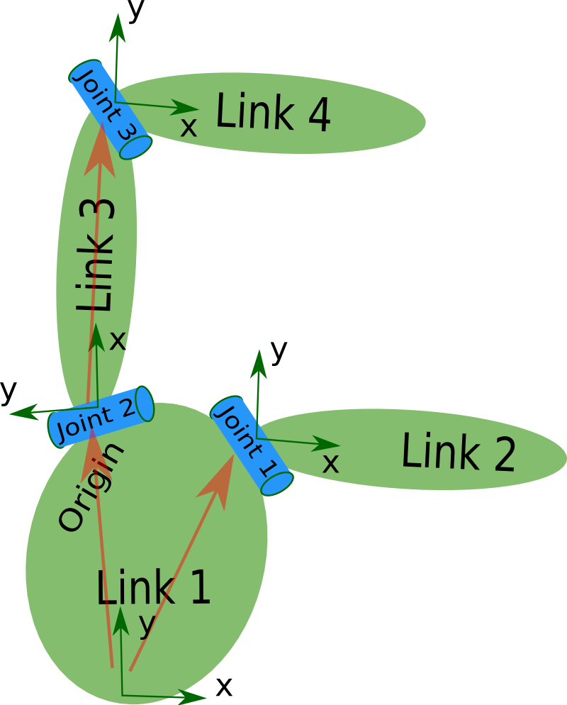
The definition of SDF coordinate frames is illustrated by the following image, in which all links are defined relative to the model, and each joint is defined relative to its child link. Since there is no offset allowed between the child link frame and the joint frame in URDF, the SDF joint poses are all zeros.

Once pose frame semantics are implemented in SDFormat, it will be possible to define an SDFormat model that behaves identically to a URDF model by specifying the parent reference frames according to the URDF convention.
Specifying joint axes in SDFormat 1.4
Joints that specify axis directions use a unit vector in the //joint/axis/xyz
element and optionally the //joint/axis2/xyz element for joints with multiple
degrees of freedom, such as universal joints.
The most intuitive frame in which to express these unit vectors is the joint
frame, and the SDFormat specification initially declared this convention.
Due to a bug in Gazebo, the primary consumer of SDFormat files at that time
(see osrf/gazebo#494),
joint axis unit vectors were interpreted in the model frame corresponding to
the joint's parent link. This was not an error in the specification, but many
models had already been written according to the incorrect implementation,
so version 1.4 of the specification was changed to match the actual behavior
at that time with the plan of reverting to the intended behavior in a
future version of SDFormat
(see //joint/axis documentation).
Specifying joint axes in SDFormat 1.5 with //joint/axis/use_parent_model_frame
In SDFormat 1.5, the default behavior is changed, so that joint axis unit
vectors are interpreted in the joint frame. For backwards compatibility,
the boolean //use_parent_model_frame element was added to //joint/axis and
//joint/axis2 with a value of true corresponding to the SDFormat 1.4
behavior and its default value of false corresponding to interpretation of
the unit vectors in the joint frame.
When forward-converting an SDFormat 1.4 file to version 1.5, the script sets
//use_parent_model_frame to true for all //axis and //axis2 elements.
Specifying parent and child link names for joints in SDFormat 1.4
Joints specify the parent and child links by name in the <parent> and
<child> elements.
The specified links must exist as siblings of the joint with one exception:
if one but not both of the parent and child links is specified as world
and a sibling link named world does not exist, the world link will be
interpreted as a fixed inertial frame.
The following model contains joint with a valid specification of sibling links.
<sdf version="1.4">
  <model name="model">
    <link name="link1"/>
    <link name="link2"/>
    <joint name="joint" type="fixed">
      <parent>link1</parent>
      <child>link2</child>
    </joint>
  </model>
</sdf>
The following models contain joints with a valid specification of one sibling link connected to a fixed inertial frame as parent or child.
<sdf version="1.4">
  <model name="model">
    <link name="link"/>
    <joint name="joint" type="fixed">
      <parent>world</parent>
      <child>link</child>
    </joint>
  </model>
</sdf>
and
<sdf version="1.4">
  <model name="model">
    <link name="link"/>
    <joint name="joint" type="fixed">
      <parent>link</parent>
      <child>world</child>
    </joint>
  </model>
</sdf>
The following model contains a link named world, so the joint connects link
to its sibling rather than connecting to a fixed inertial frame.
<sdf version="1.4">
  <model name="model">
    <link name="link"/>
    <link name="world"/> <!-- VALID, but RECOMMEND AGAINST -->
    <joint name="joint" type="fixed">
      <parent>world</parent>
      <child>link</child>
    </joint>
  </model>
</sdf>
The following model contains an invalid joint specification because the parent link does not exist.
<sdf version="1.4">
  <model name="model">
    <link name="link"/>
    <joint name="joint" type="fixed">
      <parent>fake_link</parent> <!-- INVALID: link with this name not found in this model -->
      <child>link</child>
    </joint>
  </model>
</sdf>
The following world also contains an invalid joint specification because, while
link1 does exist in the world, it is not a sibling of the joint.
<sdf version="1.4">
  <world name="world_with_invalid_joint">
    <model name="model1">
      <link name="link1"/>
    </model>
    <model name="model2">
      <link name="link2"/>
      <joint name="joint" type="fixed">
        <parent>link1</parent> <!-- INVALID: link1 is not a sibling of joint -->
        <child>link2</child>
      </joint>
    </model>
  </world>
</sdf>
This section has discussed naming conventions for <joint> elements as
children of a <model>.
For completeness, it should be noted that the SDF specification allows for a
<joint> to be a direct child of a <world>
(see world.sdf:32),
but the naming conventions for this case are not established, as this use case
is not supported by Gazebo or any other known software.
Specifying parent and child link names for joints in SDFormat 1.5 with nested models
Support for nested models was added in SDFormat 1.5, which allows a <model>
element to contain child <model>s.
For example, the following model contains two links nested inside child models.
<sdf version="1.5">
  <model name="model">
    <model name="model1">
      <link name="link"/>
    </model>
    <model name="model2">
      <link name="link"/> <!-- VALID -->
    </model>
  </model>
</sdf>
The coordinate frame of each child model is defined relative to its parent element, following the convention from SDFormat 1.4.
A joint can specify the names of parent and child links from sibling models
by specifying the sibling model name with the delimiter :: followed
by the link name.
This model contains a valid joint specification with parent and child links from sibling models:
<sdf version="1.5">
  <model name="model">
    <model name="model1">
      <link name="link"/>
    </model>
    <model name="model2">
      <link name="link"/>
    </model>
    <joint name="joint" type="fixed">
      <parent>model1::link</parent>
      <child>model2::link</child>
    </joint>
  </model>
</sdf>
This model contains a valid joint specification with a child sibling link and the parent link from a sibling model.
<sdf version="1.5">
  <model name="model">
    <model name="nested_model">
      <link name="link"/>
    </model>
    <link name="link"/>
    <joint name="joint" type="fixed">
      <parent>nested_model::link</parent>
      <child>link</child>
    </joint>
  </model>
</sdf>
Please note: The future nesting behavior, the naming rules
for child models (can they have same name as the parent model?),
and the :: delimiter are under
discussion and subject to change.
Please see the proposal
for the potential new behavior in SDF 1.7.
Phases of parsing kinematics of an SDFormat 1.4 model
This section describes phases for parsing the kinematics of an SDFormat 1.4 model.
It does not discuss proper validation of collision and visual geometries,
link inertia, and many other parameters.
There are three phases for validating the kinematics data in a model.
In libsdformat, the sdf::readFile and sdf::readString API's perform parsing
stage 1, and sdf::Root::Load performs parsing stages 1 and 2.
Each API returns an error code if errors are found during parsing.
XML parsing and schema validation: Parse model file from XML into a tree data structure, ensuring that there are no XML syntax errors and that the XML data complies with the schema. Schema
.xsdfiles are generated from the.sdfspecification files when buildinglibsdformatwith the xmlschema.rb script.Name attribute checking: Check that name attributes are not an empty string
"", and that sibling elements of the same type have unique names. This includes but is not limited to models, actors, links, joints, collisions, visuals, sensors, and lights. This step is distinct from validation with the schema because the schema only confirms the existence of name attributes, not their content.Joint parent/child name checking: For each joint, check that the parent and child link names are different and that each match the name of a sibling link to the joint, with the following exception: if "world" is specified as a link name but there is no sibling link with that name, then the joint is attached to a fixed reference frame.
After these three phases have been completed, the model kinematics can be used in several ways:
Construct a kinematic graph with a node for each link and a directed edge for each joint from the parent link to the child. The graph may be a tree if there are no kinematic loops, in which case its kinematics are compible with URDF.
Recursively compute initial frame poses for links and joints using the rules for parent frames defined in the previous section.
Phases of parsing kinematics of an SDFormat 1.5 model
Parsing an SDFormat 1.5 model is similar to parsing an SDFormat 1.4 model, with the
addition of nested models.
Validation steps 1 and 2 are the same, but the procedure for checking
parent and child names for joints must account for the :: separator,
which allows links to be specified as the descendants of sibling models
of a joint.
Phases of parsing kinematics of an SDFormat world
Parsing an SDFormat world file involves the first two steps in parsing a model followed by parsing each model according to the phases described above. The models can be parsed independently and in any order. These three phases are listed below:
XML parsing and schema validation: Parse world file from XML into a tree data structure, ensuring that there are no XML syntax errors and that the XML data complies with the schema. Schema
.xsdfiles are generated from the.sdfspecification files when buildinglibsdformatwith the xmlschema.rb script.Name attribute checking: Check that name attributes are not an empty string
"", and that sibling elements of the same type have unique names. This check can be limited to//world/model/@namesince other names will be checked in the following step. This step is distinct from validation with the schema because the schema only confirms the existence of name attributes, not their content.Model checking: Check each model according to the three phases of parsing kinematics of an SDFormat model.