
Specifying model kinematics in SDFormat
This documentation describes how SDFormat models the kinematics of
articulated multibody systems with the <model>, <link>, <joint>,
and <pose> tags, which can be briefly summarized as:
<model>: a container for links and joints that defines a complete robot or physical object<link>: a rigid body (like a "link" in a chain)<joint>: a kinematic relationship between links<pose>: the relative position and orientation between two coordinate frames
SDFormat links, joints, and models each have their own coordinate frames that
can be offset using the <pose> tag.
See the
documentation
on specifying poses for more detail on the <pose> tag.
<model>
The <model> tag serves as a named container for a group of links and joints.
Its full specification can be found
here.
Models require names using the name attribute.
For example, an empty model with no links or joints:
<model name="empty" />
A model can define a pose that offsets the model frame relative to its parent when it is inserted into a world:
<model name="model_with_pose">
  <pose>{xyz_WM} {rpy_WM}</pose>
</model>
<link>
The <link> tag represents a named rigid body and must be the child of a <model>.
Its full specification can be found
here.
Links also require the name attribute.
For example, a model with one link:
<model name="one_link">
  <link name="link"/>
</model>
All sibling elements of the same type must have unique names. Here is an example model with multiple links with unique names:
<model name="two_links">
  <link name="link1"/>
  <link name="link2"/>
</model>
A model with multiple links having the same name is invalid:
<model name="invalid_two_links_same_name">
  <link name="link"/>
  <link name="link"/> <!-- INVALID: Same name as sibling "link"! -->
</model>
Each link has a body-fixed frame, whose initial pose relative to the
model frame is specified by the link <pose> tag.
When inserted into a world, the link pose relative to the world is identical
for the following two models:
<model name="model_and_link_pose">
  <pose>{xyz_WM} {rpy_WM}</pose>
  <link name="link">
    <pose>{xyz_ML} {rpy_ML}</pose>
  </link>
</model>
<model name="equivalent_link_pose">
  <link name="link">
    <pose>{xyz_WL} {rpy_WL}</pose>
  </link>
</model>
<joint>
The <joint> tag represents a kinematic relationship between rigid body links
that constrains the degrees of freedom between those links.
It must be a child of a model.
Its full specification can be found
here.
There are several different types of joints that can be specified in the
type attribute.
The supported joint types are listed below along with the number of degrees
of freedom remaining between the two links.
ball: 3 rotational degrees of freedomcontinuous: 1 rotational degree of freedom with no joint limitsfixed: 0 degrees of freedomprismatic: 1 translational degree of freedomrevolute: 1 rotational degree of freedom with joint limitsscrew: 1 coupled rotational/translational degree of freedomuniversal: 2 rotational degrees of freedom
The parent and child links of a joint are specified by the <parent> and
<child> tag respectively. These tags refer to other links inside the model by
their names. For example, the following model contains two links and a fixed
joint between the links:
<model name="two_links_fixed">
  <link name="link1"/>
  <link name="link2"/>
  <joint name="joint" type="fixed">
    <parent>link1</parent>
    <child>link2</child>
  </joint>
</model>
As discussed in the previous section, the specification requires all sibling elements of the same type to have unique names. This technically permits a sibling link and joint to have the same name, such as the following example, but this is not recommended as it can lead to confusion and may be disallowed by a future version of the spec.
<model name="sibling_link_joint_namesake_not_recommended">
  <link name="base"/>
  <link name="attachment"/>
  <joint name="attachment" type="fixed">
    <parent>base</parent>
    <child>attachment</child>
  </joint>
</model>
<joint><axis>
For joint types that have one or two degrees of freedom, the properties of the
axes of rotation/translation are specified by the <axis> and <axis2> tags.
Both tags contain the <xyz> tag which specifies the the unit vector along the
axis of motion. In SDFormat versions 1.4 and earlier, this unit vector is
expressed in the parent link's model frame. In SDFormat versions 1.5 and 1.6, by
default, the unit vector is expressed in the joint frame that contains the
<axis> tag. However, the tag <use_parent_model_frame> can be set to true to
specify the unit vector in the parent link's model frame instead. This is used to
replicate the behavior of the <xyz> tag in v1.4 and earlier. Note that the
<use_parent_model_frame> tag may be removed in a future version of SDFormat.
For example:
<model name="joint_axis">
  <link name="A"/>
  <link name="B"/>
  <link name="C"/>
  <joint name="J1" type="revolute">
    <pose>0 0 0 1.57 0 0</pose>
    <parent>A</parent>
    <child>B</child>
    <axis>
      <xyz>0 0 1</xyz> <!-- The xyz unit vector is expressed in the joint frame -->
    </axis>
  </joint>
  <joint name="J2" type="revolute">
    <parent>B</parent>
    <child>C</child>
    <axis>
      <xyz>0 0 1</xyz> <!-- The xyz unit vector is expressed in the parent link's model frame. Thus, this axis is orthogonal to the axis of J1 -->
      <use_parent_model_frame>true</use_parent_model_frame>
    </axis>
  </joint>
</model>
<joint><pose>
For a joint with parent link frame P and child link frame C,
the joint <pose> tag specifies the pose X_CJc of a joint frame Jc rigidly
attached to the child link.
Similarly, a frame Jp is rigidly attached to the parent body.
These frames are illustrated in the following figure.

The pose of frame Jp in P is not specified explicitly but is inferred
from the poses of P and C given in the model frame at the "zero
configuration" of the joint.
Most joint types specify how the frames Jp and Jc can move relative
to each other (with the notable exception of the fixed joint).
A zero configuration is defined for each joint type (for instance, zero angle
for a revolute joint) such that the frames Jp and Jc are coincident in the
zero configuration.
While a <pose> tag is not necessary for a fixed joint, it is used regularly
in other joint types.
See the following example for an illustration of the joint pose.
Example Joint: revolute
The rotational axis of a revolute joint is specified by a
unit vector in the <xyz> tag under the <axis> element.
By definition, this axis has the same coordinates when expressed in either
frame Jp or Jc.
The joint pose and axis direction for the following SDF model are illustrated
in the following figure, with model frame M, parent link frame P,
child link frame C, and the child joint frame Jc.
<model name="two_links_revolute">
  <link name="Parent">
    <pose>{xyz_MP} {rpy_MP}</pose>
  </link>
  <link name="Child">
    <pose>{xyz_MC} {rpy_MC}</pose>
  </link>
  <joint name="joint" type="revolute">
    <pose>{xyz_CJc} {rpy_CJc}</pose>
    <parent>Parent</parent>
    <child>Child</child>
    <axis>
      <xyz>{xyz_axis_Jc}</xyz>
    </axis>
  </joint>
</model>

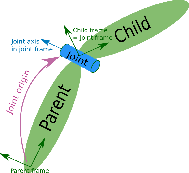
Note that coordinate frames are defined differently in URDF.
The kinematic topology of a URDF file must be a tree with no closed
kinematic loops, and frames are defined recursively along each chain of
links and joints.
As discussed in the
pose documentation,
the <origin> tag is the URDF analog of the SDFormat <pose>.
The joint origin defines the pose X_PJp of the joint frame Jp in the parent
link frame.
The joint frame Jc is rigidly attached to the child link such that it coincides
with Jp in the zero configuration,
and the child link frame is co-located with frame Jc.
This is illustrated in the URDF documentation
with the following image and a corresponding URDF snippet:
<!-- URDF -->
<robot name="two_links_revolute">
  <link name="Parent"/>
  <link name="Child"/>
  <joint name="joint" type="revolute">
    <origin xyz="{xyz_PJc}" rpy="{rpy_PJc}" />
    <parent link="Parent"/>
    <child link="Child"/>
    <axis xyz="{xyz_axis_Jp}" />
  </joint>
</robot>
Example Models
In this section, a revolute joint is used to further demonstrate
the use of the <pose> tag with concrete examples.
In these examples, the joint pose is set so that at the initial configuration,
the displacement vectors from the joint to each link are orthogonal to each other.
Model two_links_orthogonal_1
In the first example, the xyz component of the joint pose is set to 0 0 -0.1.
Since the pose is specified
relative to the child link (linkB), the position of the joint in the world
frame is 0.1 0 0.
<model name="two_links_orthogonal_1">
  <link name="linkA">
    <pose>0 0 0 0 0 0</pose>
  </link>
  <link name="linkB">
    <pose>0.1 0 0.1 0 0 0</pose>
  </link>
  <joint name="jointAB" type="revolute">
    <pose>0 0 -0.1 0 0 0</pose>
    <parent>linkA</parent>
    <child>linkB</child>
    <axis>
      <xyz>0 1 0</xyz>
    </axis>
  </joint>
  <joint name="joint_world" type="fixed">
    <parent>world</parent>
    <child>linkA</child>
  </joint>
</model>
The initial configuration of this model is shown in the following figure.

Model two_links_orthogonal_2
In the second example, the parent and child links have the same pose relative
to the model frame, but the xyz component of the joint pose is set to -0.1 0 0.
This changes the position of the joint in the world frame to 0 0 0.1.
Note that the pose of linkB and link2 is the same in both models.
<model name="two_links_orthogonal_2">
  <link name="link1">
    <pose>0 0 0 0 0 0</pose>
  </link>
  <link name="link2">
    <pose>0.1 0 0.1 0 0 0</pose>
  </link>
  <joint name="joint12" type="revolute">
    <pose>-0.1 0 0.0 0 0 0</pose>
    <parent>link1</parent>
    <child>link2</child>
    <axis>
      <xyz>0 1 0</xyz>
    </axis>
  </joint>
  <joint name="joint_world" type="fixed">
    <parent>world</parent>
    <child>link1</child>
  </joint>
</model>
The initial configuration of this model is shown in the following figure.

Comparison after joint motion
In both examples, the <axis> tag is used to specify the axis of rotation of
the revolute joint. This axis is specified relative to the joint
frame.
The model configurations for joint values of 0.78 radians (~45 degrees) are shown in the following figure. Note that this results in two very different poses for linkB and link2 even though they had the same initial world pose.
